3D Scanning and Printing
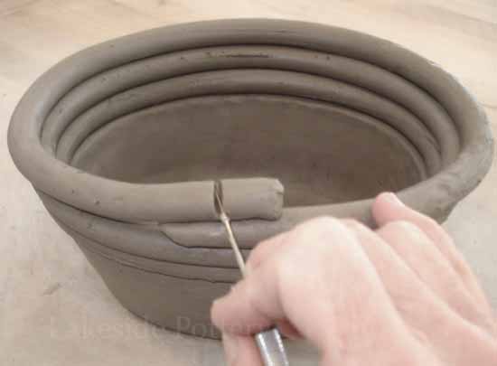 My undergraduate background was in ceramics. 3D printing is one of the few means of digital fabrication that, like ceramics, is additive instead of subrtactive. I was interested in exploring the correlation between pottery and 3D printing, which to me is a delightful comparison of incredibly old fabrication technique and one of the newestways of making forms. I decided that the most obvious parallel to 3D printing process is coil building, in which long snake-like rolls of clay are spiraled up to create a hollow cylindrical body.
A 3D printer works in almost the exact same way, by depositing a continuously extruded material in built up layers to create a form. I collect ceramic vessels, and so I decided to create a simple cup that incorporated both ceramic and digital processes. Traditional japanese pottery adopts an aesthetic that embraces imperfections and values the mark of the artist's hand. A simple cup should be functional, beautiful, and tactile. I like non-traditional handles, often a textured patch or raised form or even a dent in the body of the cup.
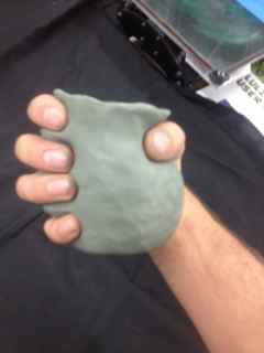
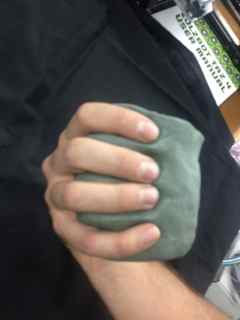
I made a rough form in modeling clay that fully embraces the artists hand.
From here I went into the digital production. I scanned my cup with the 3D scanner. Initial attempts were unsuccessful and lacked definition, so I discovered it was easier to place the cup on a bucket on an office chair. By rotating the object on the swivel chair and keeping the scanner stationary, I was able to get a cleaner more stable scan of the object(and there's another corrolary to a ceramic process, the throwing wheel!)
The mesh still had a lot of holes and irregularities, so I imported it into rhino where I used mesh commands to clean up the geometry and crop out the excess scanned parts. once I was happy with the general form I used grasshopper to script the rest of the ultimate form.
I wanted to have a more direct relationship to the coil building process, so I decided that instead of a solid I would control the paths of the printer nozzle directly through linework. I took countour lines of the mesh at a fairly large interval of .3mm because I wanted a chunkier resolution that would show the fabrication process and relate to the ceramic counterpart. I then manipulated the contours in a series of steps.
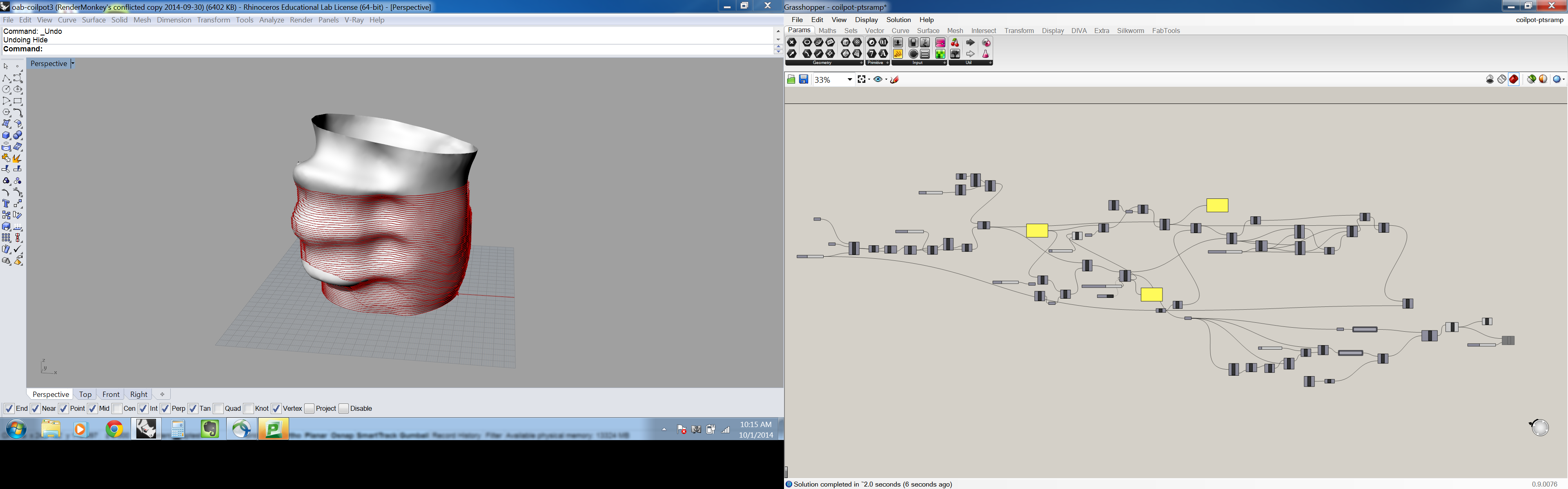
1. I cleaned up the lines by taking a series of planes arrayed radially about the center of the cup and joining points where the contours and planes intersected.
2. I made sure that the step-over for each successive coil would be small enough to ensure that the material would be deposited on the previous coil. This is done through a recursive script that draws each successive coil a maximum of .2mm laterally from the previous coil.
3. I was concerned that a single shell would be too thin, so I offset each curve .3mm to create thicker walls.
4. In order to create a single polyline to use as a toolpath, I ramped the outside offset so that it would raise up the thickness of one layer with each revolution on the cup and joined all the lines together in a single polyline.
After I had generated the linework, I used Silkworm, a Grasshopper plugin, to output the Gcode. The specific settings of the machine like temperature, feedrate, extrusion rate, etc. are included in the Gcode, so I exported a generic code from a sample file, opened it up in notepad, and cut and pasted my code into it. Because makerBot uses a proprietary code, I instead used the LulzBot Taz to print my cup.
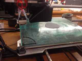
The Taz requires a bit of fiddling to get it to work right. First we had to level the bed. We move the nozzle to various points on the bed and then used a hex wrenchto raise and lower it so that a sheet of paper would just barely fit under the nozzle. It turns out the bed was warped and was higher in the middle, so it took a bit of fiddling to get it right. Then, we couldn't get the ABS to stick to the table. Eventually we got it to work after we cleaned the table with isopropyl alcohol, applied tha ABS primer, and fiddled with nozzle and bed temperature controls.
 Initially, I had two seperate files, one for the base and one for the walls of the cup. Unfortunately, because I used the software for the printer to develop the Gcode for the base and the walls were done in Grasshopper, they ended up with two different coordinate systems and completely missed each other! To remedy this, I worked out the Gcode for both elements in grasshopper and then they worked fine.
Now it's working!
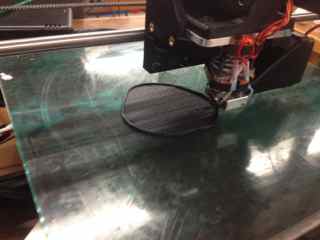
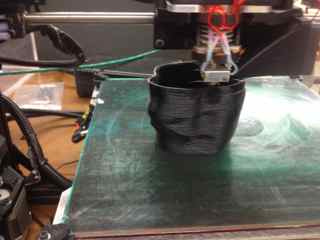
The cup printing
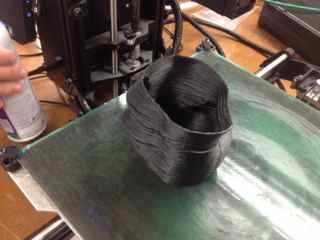
and the final product!
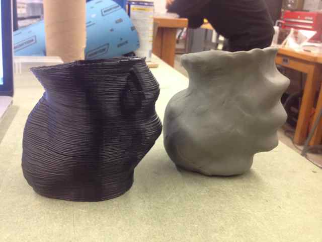
It is interesting to see how much the script changed the form of the 3D printed object. I would be interested to subtract one volume from the other to visualize how much it actually changed. I would also be interested to adjust feedrates and contour levels to see what kind of effects I can get. Perhaps a true single coil pot would be acheivable if I used a higher extrusion rate and a slower tool velocity to get thicker walls.